
 Search products
 en
en 简体中文
简体中文 русский
 Español
ZN-L1165 Vertical Machining Center
Cat:Vertical Machining Center
This series of machining center is fixed in A-shape single column, mobile structure of workbench, high rigidity of basic parts, lightweight of moving ...
See DetailsWhen a job shop receives a request for 600 aluminum brackets, each needing two drilled holes, one tapped hole, and a milled pocket, the production engineer faces a familiar decision. A five-axis machine could access every face in one setup, but the workpiece only needs tool access from one side. Holding the part, programming toolpaths, and monitoring tool wear all point in the same direction: a three-axis CNC vertical machining center. This scenario is not an exception. It represents a large share of everyday contract CNC machining.
A 3-axis CNC vertical machining center keeps the spindle in a vertical position and forms the cut through motion along X, Y, and Z. The workpiece remains fixed to the table while the tool approaches from above. That arrangement is highly efficient for prismatic components, meaning parts in which functional features sit on flat planes and along a fixed vertical orientation.
Operations commonly performed include:
None of these operations require tilting the tool. That is where the practical advantage comes from: programming stays close to the drawing dimensions, setup mistakes are easier to trace, and the operator can trust the original datum reference throughout the cycle.
Do not evaluate a machining center by axis count alone. Evaluate it by the number of jobs it can finish predictably without a second setup.
Parts that benefit most from a 3-axis vertical center have one dominant reference face. The design defines most or all critical tolerances from that face, and the machine can hold those tolerances without extra rotational axes. A motor mounting plate is a good example: the seal face, the bolt circle, and the dowel holes all live in the same coordinate system.
Many components described as three-dimensional are actually 2.5-D when analyzed from a machining perspective. Their datums, pockets, and boss heights are parallel, and most hole axes are perpendicular to a planar datum. That geometry is ideal for a 3-axis vertical machining center.
A three-axis center cannot reach the underside of a feature or machine undercuts behind overhangs. Those geometries require a second part orientation, an indexing fixture, or an additional rotary axis.
Across industries, the applications of 3-axis CNC vertical machining centers follow the same logic: a family of parts with stable flats, frequent holes, and controlled setup variety. The most common areas include mold manufacturing, automotive suppliers, new-energy hardware, and general job shops.
In mold construction, cavity plates, bolster plates, stripper plates, and insert pockets are machined from rectangular blocks with reliable reference surfaces. A rigid 3-axis vertical center performs the initial roughing, precision drilling, cooling-hole preparation, and finishing passes on faces that open upward. During mold repair, the same machine can resurface worn areas or blend welded sections before final assembly.
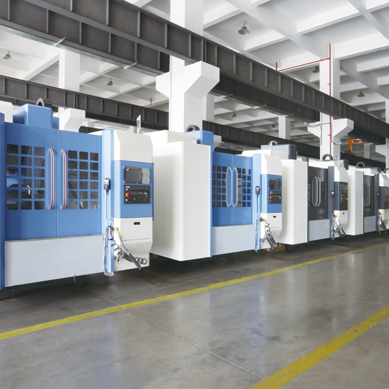 Vertical Machining Center for Mold and Automotive CastingsThis machining center offers rigid construction and automatic tool changing, suited for drilling, tapping, and finishing on castings and mold plates. Its spindle cooling and chip flushing support consistent accuracy in batch production.View Product →
Automotive suppliers often receive aluminum or iron castings with tight bores, gasket faces, and large numbers of threaded holes. A vertical machining center with an automatic tool changer can move through drills, taps, end mills, and reamers with limited operator intervention. Typical work includes water-pump housings, oil-filter adapters, electric-drive end covers, mounting brackets, and coolant manifolds, especially when batch sizes do not justify fully dedicated automation.
The new-energy sector brings a different mix of long, light components and compact precision housings. Battery-pack frames, busbar holders, inverter housings, and mechanical spacers need clean edges, accurate hole pitch, and repeatable tapping patterns. A 3-axis vertical machine can handle these tasks efficiently because most features are accessible from one vertical orientation. Through-spindle coolant and positive chip evacuation become especially useful in the deep, repetitive drilling sequences found in this type of work.
General machine shops use a 3-axis vertical machining center as the default machine for fixture plates, prototype housings, maintenance parts, and batch quantities from one to one hundred pieces. The machine wins because setup time is short, CAM programming is direct, and a wide range of materials can be cut without changing the fundamental process. When the next order arrives with a completely different shape, the same machine can be reprogrammed and running again by the afternoon.
| Application Area | Typical Workpiece Shape | Expected Operations | Machine Emphasis |
|---|---|---|---|
| Mold and die | Cavity plates, bolster plates, insert blocks | Roughing, flat finishing, drilling, light profiling | Structural rigidity, thermal stability, repeatability |
| Automotive | Brackets, pump bodies, motor end covers, manifolds | Facing, pocket milling, drilling, tapping | Spindle torque, automatic tool changing, chip disposal |
| New energy | Battery frames, busbar holders, inverter housings | Edge milling, repetitive drilling and tapping | Work envelope, reliable coolant delivery, quick cycles |
| Job shop and prototype | Fixtures, small housings, repair parts | Mixed milling, drilling, tapping, occasional reaming | Faster setup, wide spindle range, stable software support |
In a 3-axis machine, the axis count only describes the motion geometry. The actual result depends on structural rigidity, damping, spindle torque, thermal behavior, and the quality of the control system. Two machines with identical travels and spindle speed ratings can produce meaningful differences in surface finish when cutting steel or holding a tight bore position.
The vertical column and one-piece base must absorb cutting forces without twisting or vibrating. Understanding how rigid base design supports machining accuracy helps a buyer separate real capability from a headline spindle speed.
Check the speed-torque curve before comparing maximum rpm. A lightly built spindle that reaches high rpm only under no load will not give the same results when tapping steel or when a wide face mill hits an interrupted cut.
Machine selection should begin with the shape envelope after fixtures are added, not with the raw stock dimensions. From that starting point, compile the number of tools in your most common programs, the dominant material, and the most demanding surface finish. A machine that is correctly sized for that mix will be more useful than one selected purely by maximum table load or rapid traverse rate.
Choose a machine with some capacity for near-sibling variation. The best purchase is not the one that fits today only; it is the one that easily handles the small design changes arriving after production release.
To see how these requirements translate into contemporary equipment, reviewing the vertical machining center range from a structural and functional standpoint is more useful than comparing travel numbers alone.
The applications of 3-axis CNC vertical machining centers are best summarized by the phrase “stable, repeatable access from one setup.” When a part geometry can be produced with clear datum references, vertical drilling, and conventional milling tools, the three-axis vertical center is often the lowest-cost route to a good part. It does not replace advanced multi-axis machining centers. It simply handles the everyday majority of metal removal that keeps a shop productive.
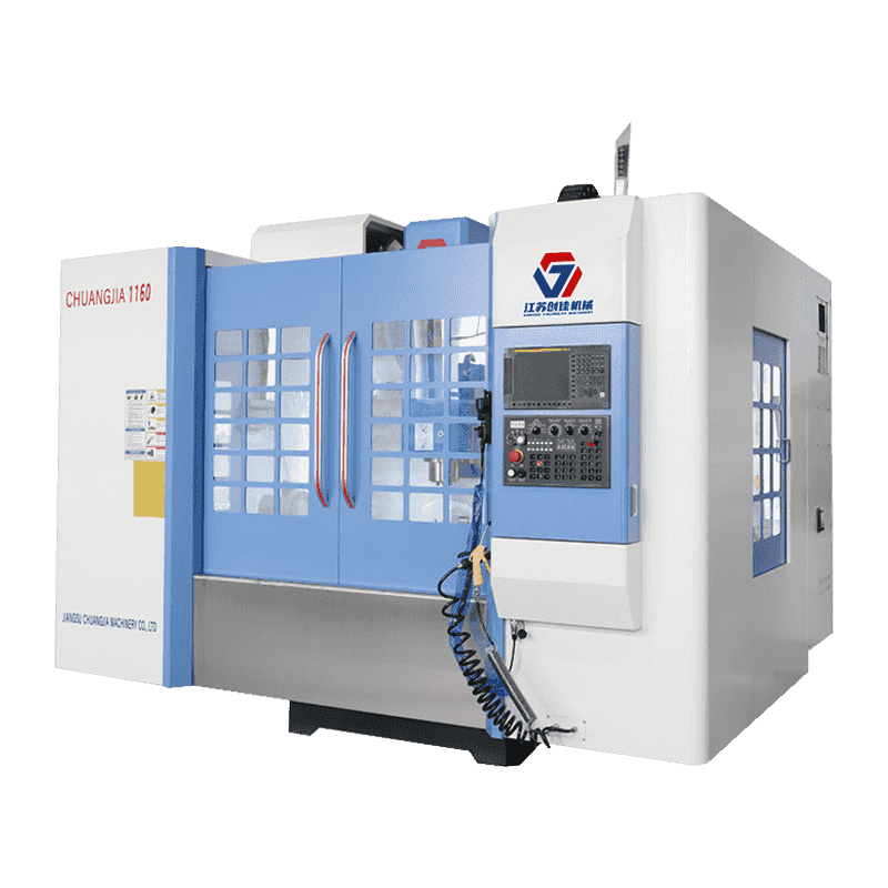
This series of machining center is fixed in A-shape single column, mobile structure of workbench, high rigidity of basic parts, lightweight of moving ...
See Details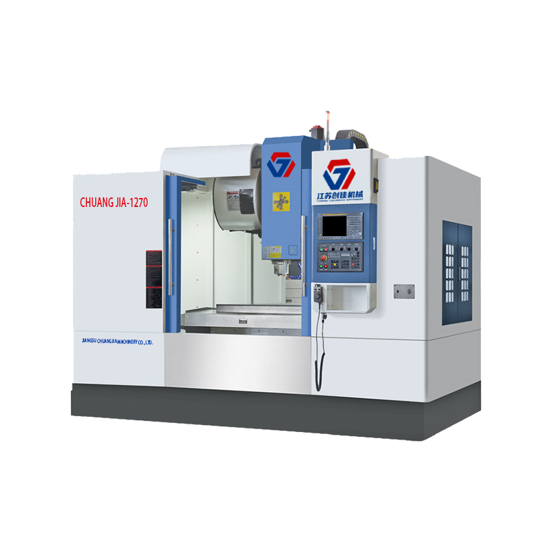
This series of machining center is fixed in A-shape single column, mobile structure of workbench, high rigidity of basic parts, lightweight of moving ...
See Details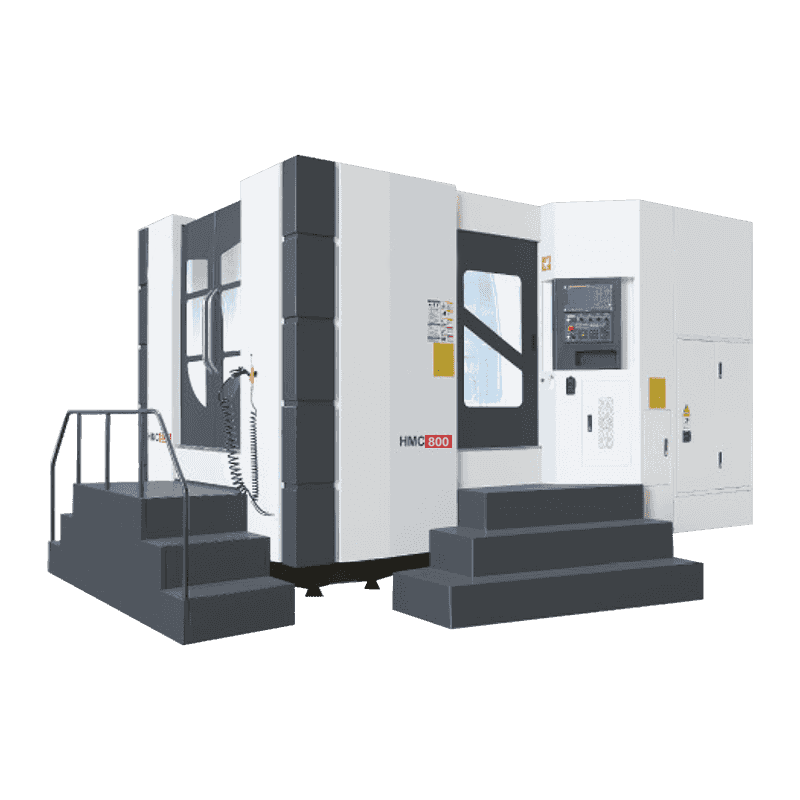
The bed adopts inverted T structure layout, the table moves around (X axis), the headstock moves up and down (Y axis) and the column moves back and fo...
See Details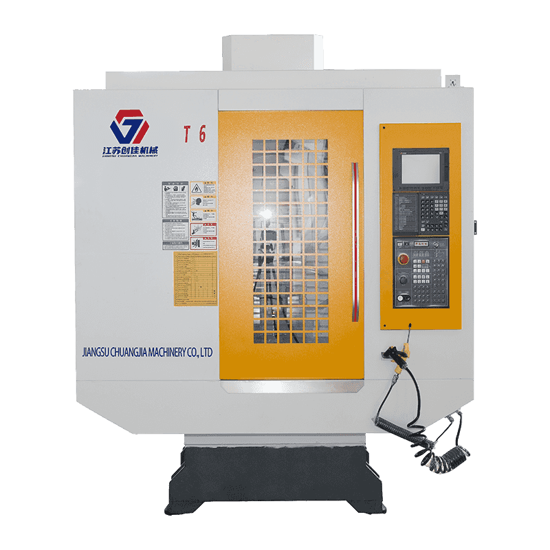
Drilling and tapping center ZN-T6 has easy operability, high reliability, ultra-high cost performance, mainly used in general industry, hardware, medi...
See Details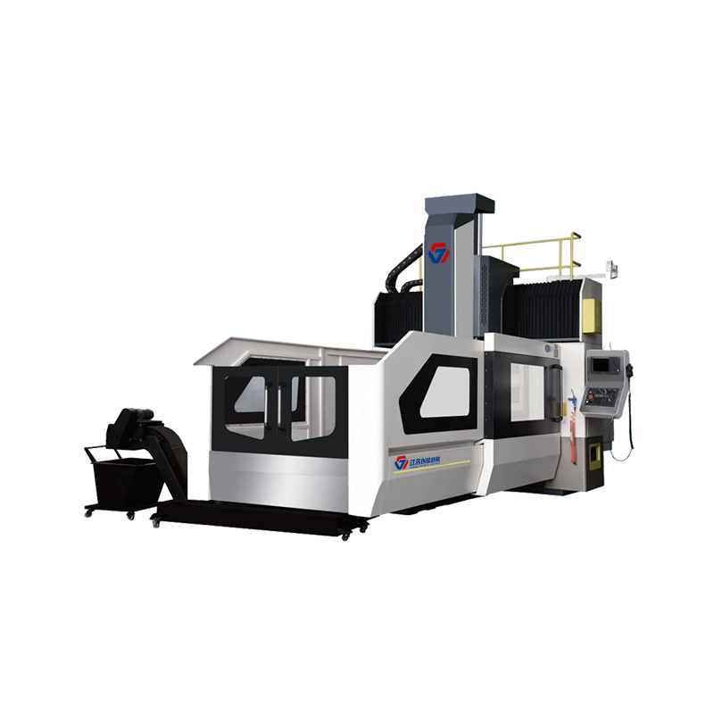
The machine adopts the structure form of fixed gantry frame and moving table on the bed. Beam column integrated design, has the characteristics of hig...
See Details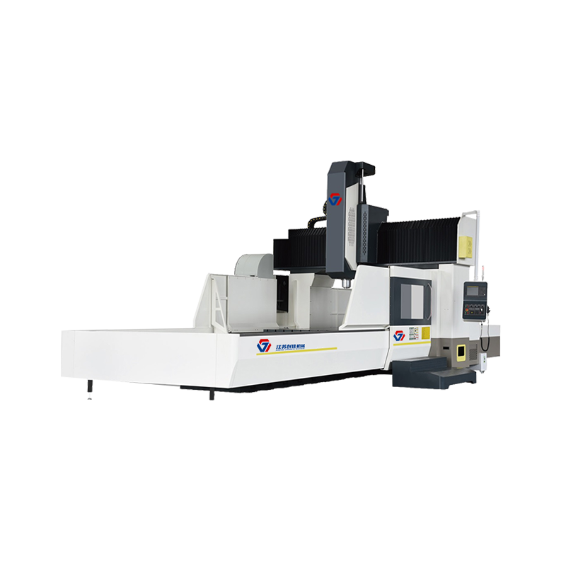
The machine adopts the structure form of fixed gantry frame and moving table on the bed. Beam column integrated design, has the characteristics of hig...
See Details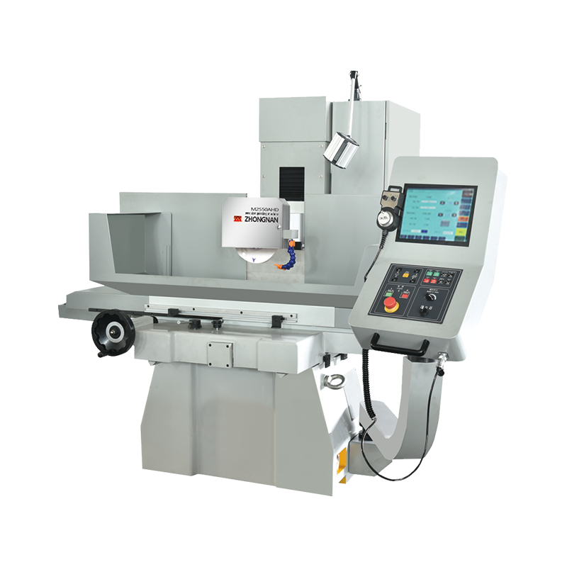
High precision/High speed/easy to operate CNC surface grinding machine X axis hydraulic /YZ axis servo/CNC system. Cross slide structure, double V rai...
See Details
The machine adopts the structure form of fixed gantry frame and moving table on the bed. Beam column integrated design, has the characteristics of hig...
See Details
All rights reserved Jiangsu Chuangjia Machinery Co., LTD.
