
 Search products
 en
 简体中文
 русский
 Español
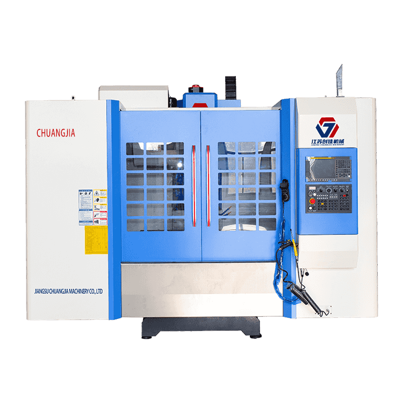
ZN-V1160 Vertical Machining Center
Cat:Vertical Machining Center
This series of machining center is fixed in A-shape single column, mobile structure of workbench, high rigidity of basic parts, lightweight of moving ...
See DetailsA fourth axis rarely makes a machine faster. It removes the setup where your tolerance was lost, and that is the only sound reason to pay for it.
A valve body reaches the table with bores on three faces and a 0.02 mm positional callout between two of them. On a three-axis vertical machining center that is three setups and three datum resets. On a 4 axis CNC vertical machining center it is one setup and one datum. That difference, not the spindle speed in the brochure, is what the fourth axis is bought for.
So the conclusion first: the fourth axis pays for itself when a part family has machined features on more than two faces, the workpiece can be gripped around a rotary axis, and the batch repeats often enough to absorb the rotary unit, the tailstock, the CAM post-processor and the operator training. If any one of those three conditions fails, a three-axis machine with better workholding will usually make the same part for less money.
Rule of thumb: if repositioning the part between setups costs more than 10 percent of the cycle time, and a chuck or a center can hold it, run the four-axis numbers before ordering another three-axis machine.
On a vertical machining center the fourth axis is almost always a rotary table mounted on the standard table, turning the workpiece around the X axis, which is the A axis. The spindle still travels in X, Y and Z. What changes is that the part can be presented to the tool at an angle instead of being unclamped and turned by hand.
In indexed mode the rotary table positions the part at a fixed angle, clamps, and cutting resumes; the control treats it as an extra positioning axis. Standard CAM output usually covers this, and the rotary unit only needs solid positioning accuracy.
In simultaneous mode the A axis moves while the tool is in the cut, which is how wrapped profiles, spiral ports and cam forms are generated in one continuous pass. That demands a post-processor that understands rotary kinematics, a control with the rotary drive integrated rather than added later, and a programmer who has run four-axis work before.
A fourth axis on a vertical machine holds the part on a horizontal rotary axis beneath a vertical spindle: fixturing stays visible, chips fall clear, and tooling is standard. A horizontal machine with a rotary pallet reaches more faces per pass and clears chips from deep bores better, but it costs more and usually needs a tombstone fixture. Below roughly a 500 mm cube, vertical is normally the cheaper place to start.
| Configuration | Motion | Setups for a multi-face part | Typical fit | Main trade-off |
|---|---|---|---|---|
| Three-axis VMC | X, Y, Z | Two to four | Plates, single-face work, low volume | Datum resets between setups |
| Indexed 3+1 | X, Y, Z plus A positioning | One to two | Features at fixed angles around the part | No continuous rotary interpolation |
| Simultaneous four-axis | X, Y, Z plus interpolated A | One | Wrapped profiles, cams, spiral ports | CAM post and clearance checks |
| Five-axis | Three linear plus two rotary | One | Complex contours and undercuts | Higher machine, programming and collision cost |
The work that justifies a fourth axis is rarely exotic. It is repeated, and the angular relationship between faces has to hold from one part to the next. Four families come up again and again:
The fourth axis seldom shortens the cut. It deletes the setup, and the setup is where most of the tolerance disappears.
Automotive, new energy, mold making and sapphire processing are the sectors where this pattern shows up most often. Volume is what changes the arithmetic: at a few hundred parts a month, the time saved per piece outweighs the flexibility of hand fixturing.
The most common specification error is sizing the machine for the length of the part and forgetting its swing. A workpiece 300 mm long and 220 mm across needs a rotary unit that can grip it, a swing envelope that clears the column, and enough Z travel left to reach the top face. A 250 mm rotary unit can consume 200 to 250 mm of Z travel before a part is even loaded.
A 1270 mm class machine with an automatic tool changer is a common middle ground: enough X travel for a rotary table and tailstock side by side, enough Z to clear the rotary body, and a magazine deep enough to finish a mixed drilling and milling program without stopping.
Check the interference drawing, not the catalogue photograph. On many vertical machining centers the tool changer and a large rotary table share space, and the maximum swing with a full magazine is smaller than the swing with the tools you happen to be running today.
A rotary axis is only as accurate as the way the part is held. Between centers suits shafts; a three-jaw chuck or a self-centering vise suits short cylinders; a faceplate with custom nests suits awkward castings. Each choice changes how much of the part hangs unsupported, and unsupported length shows up as chatter.
Rotary accuracy is quoted in arc-seconds, and that conversion is worth doing by hand. A rotary axis accurate to 15 arc-seconds, measured at a 300 mm radius, contributes roughly 0.02 mm of tangential error before spindle error, thermal growth or tool wear is added. On a 0.05 mm true position callout, that is already a large share of the budget.
Continuous rotation also warms the rotary unit. A table that indexes a few times per cycle stays near ambient; one that interpolates for twenty minutes drifts, and the drift lands in the angular relationship between features. Machines built for that work carry more mass in the base and column, and the accuracy story starts below the table, as covered in rigid base structures and machining accuracy.
Do not plan on bolting a rotary table onto a three-axis machine later. The control needs a fourth-axis drive and wiring, the geometry has to be re-verified, and aftermarket rotary units can complicate warranty and service. If the part family is real, order the axis with the machine.
Because a four-axis vertical machining center is a configuration rather than a catalogue item, engineering depth matters as much as the specification sheet.
Jiangsu Chuangjia Machinery is one builder with that kind of vertical integration. Founded in 2000 as a surface grinder manufacturer and now part of the Nantong Zhongnan Intelligent Technology group, it runs a production park of about 100,000 square meters with more than 380 employees, including 30 senior engineers and 20 R&D engineers, and it operates its own foundry, sheet metal shop and paint shop alongside machining and assembly.
Its vertical machining center range covers the ZNL1160, ZNL1270, ZNL1580 and ZNL1890 models plus the ZNV1160, ZNV850 and ZNV855, with automatic tool changers specified on the ZNL1270 and ZNV855. The same group also builds gantry and horizontal machining centers, tapping centers and precision surface grinders.
A useful test during a factory visit: walk from the foundry to the machining bays to the alignment benches without leaving the site. In-house castings and in-house alignment are what let a four-axis configuration hold the same geometry standard as the three-axis version of the same machine.
Buy the fourth axis when the part family is real, the batches repeat, and the workpiece can be gripped around a rotary axis. Specify it at the order stage together with the rotary unit, the tailstock and the control options, rather than treating it as an accessory to be added later.
Then spend the specification effort where it shows up in the part: swing diameter, remaining Z travel, tool clearance and the rigidity of everything underneath the table. Get those right and the fourth axis does what it was meant to do, which is one setup, one datum, and a tolerance that survives to the second face.
This series of machining center is fixed in A-shape single column, mobile structure of workbench, high rigidity of basic parts, lightweight of moving ...
See Details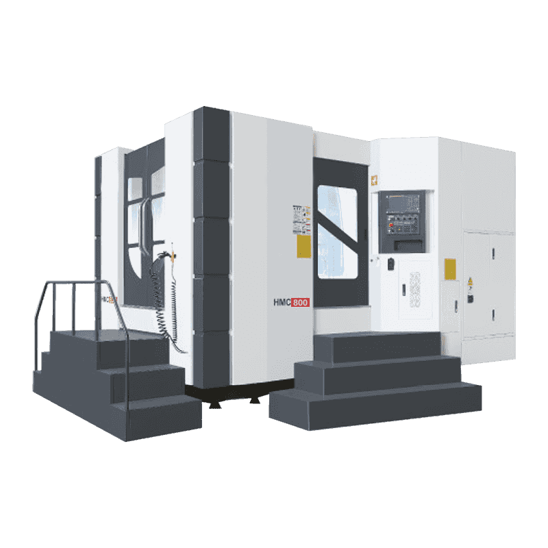
The bed adopts inverted T structure layout, the table moves around (X axis), the headstock moves up and down (Y axis) and the column moves back and fo...
See Details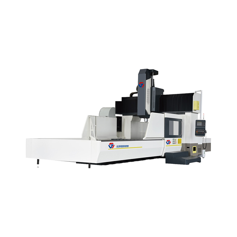
The machine adopts the structure form of fixed gantry frame and moving table on the bed. Beam column integrated design, has the characteristics of hig...
See Details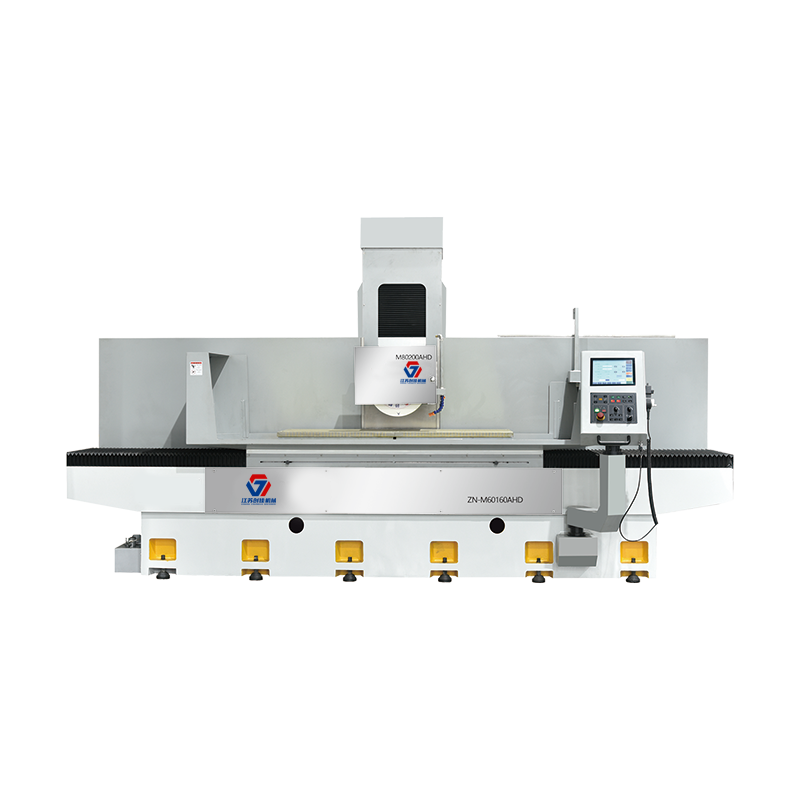
The machine tool is mainly suitable for the precision grinding of various metal materials, such as plane, step and specific shape, and is widely used ...
See Details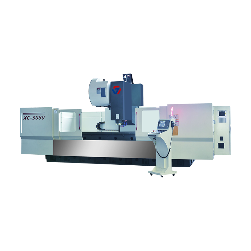
Mainly process the internal profiles of rail transit locomotives; Narrow and long parts of automobiles; TV frames, refrigerator frames, communication ...
See Details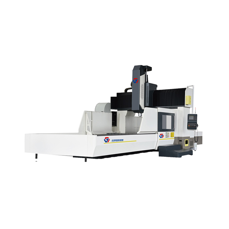
The machine adopts the structure form of fixed gantry frame and moving table on the bed. Beam column integrated design, has the characteristics of hig...
See Details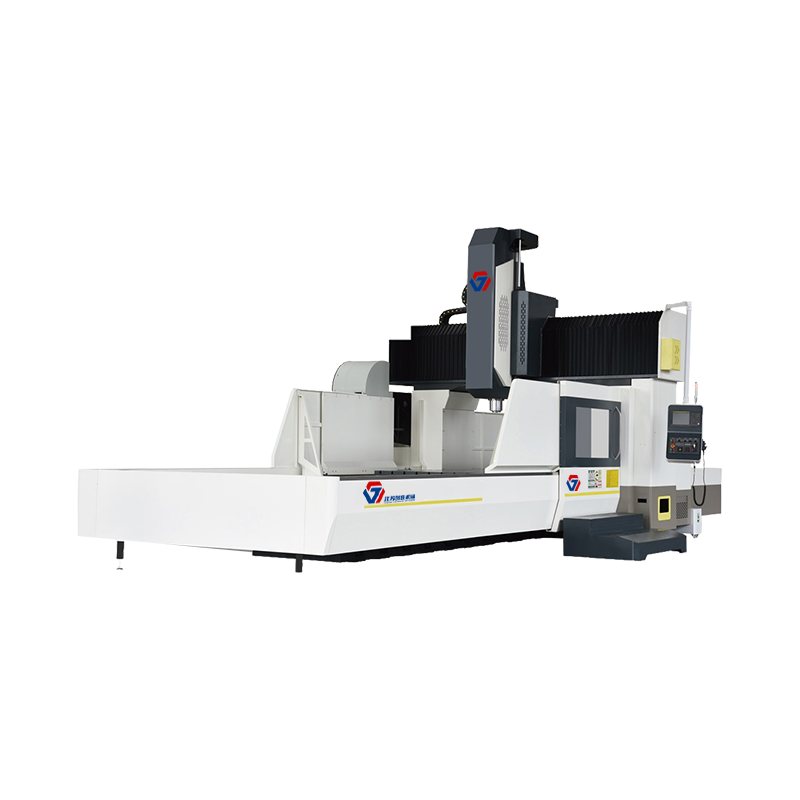
The machine adopts the structure form of fixed gantry frame and moving table on the bed. Beam column integrated design, has the characteristics of hig...
See Details
The machine adopts the structure form of fixed gantry frame and moving table on the bed. Beam column integrated design, has the characteristics of hig...
See Details
All rights reserved Jiangsu Chuangjia Machinery Co., LTD.
